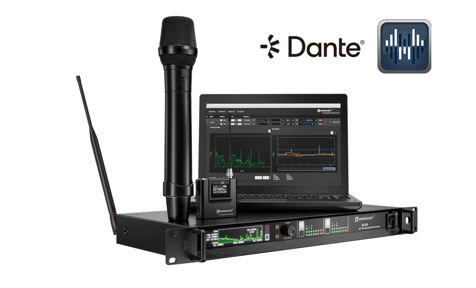
Every number a supplier prints should be reproducible from the hardware in the box - receiver, transmitters and the software that monitors them.
A datasheet is not marketing copy; it is the technical annex to your purchase contract. Yet most of the numbers on a professional wireless microphone datasheet are quoted without the conditions that give them meaning, and two suppliers can print the same figure while promising completely different hardware. This guide walks the rows in the order an engineer would: what each specification actually commits a supplier to, which conditions to check, and which missing rows tell you more than the printed ones.
Every example below is drawn from the published specifications of receivers on this site - the UR-2Q, the UR-280 and the HR-32D - so you can verify each claim against a live product page while you read.
Sensitivity: Three Numbers That Only Work Together
Receiver sensitivity is quoted as a trio: an RF input level, a deviation, and the signal-to-noise ratio achieved at that combination. Our quad-channel receiver, for example, specifies 5 dBμV input at 25 kHz deviation with S/N above 60 dB. All three parts carry meaning. The input level says how weak a transmitter signal the receiver can still work with; the deviation says how much the carrier is being frequency-modulated; the S/N figure says how clean the recovered audio is under exactly those conditions.
The trap is comparing sensitivity rows that use different conditions. "S/N > 60 dB" alone is not a specification - it is a fragment. If a datasheet prints an SNR figure without the input level and deviation that produced it, ask for the full conditions before you compare it with anything. A well-documented receiver states the trio in one line; that habit alone tells you something about the engineering culture behind it.
Signal-to-Noise: 105 dB or 110 dB? Check the Chain
Our dual-channel UR-280 quotes S/N above 110 dB; the UR-2Q and the HR-32D quote above 105 dB. The difference is not quality - it is which part of the chain the number describes. The 105 dB figures sit alongside a 96 kHz / 24-bit audio sampling specification: they describe the digital audio chain after conversion. The 110 dB figure describes the analogue audio output stage of a receiver whose whole job is delivering two channels cleanly.
Both are legitimate specifications. The error is comparing them across different chain definitions as if they were competing claims. When you audit any supplier's numbers, ask which stage the measurement covers - RF-to-conversion, or conversion-to-output - and insist that the same stage is used for every unit you compare. A datasheet that defines its measurement points explicitly is doing the work of making itself comparable; treat that as a positive signal about everything else in the document.
THD: What "@1 kHz" Actually Commits To
Total harmonic distortion appears on our datasheets as T.H.D < 0.7% at 1 kHz on the quad-channel receiver and < 0.5% at 1 kHz on the UR-280. The suffix does most of the work: the figure is measured at a 1 kHz test tone, which is the industry's standard reference point for audio equipment measurements under the IEC 60268 series.
Two reading notes. First, a 1 kHz figure is a commitment about the midband, where most programme content lives - it is a meaningful floor, not the whole story, and a supplier quoting a full-band THD sweep is offering more information, not a better one. Second, distortion interacts with deviation: at low RF input levels, limiting and noise recovery raise distortion, which is why honest THD figures come tied to the same conditions as the sensitivity trio. A THD row that floats free of conditions is decoration, not a specification.
Frequency Response: Tolerance Beats Endpoints
Endpoint numbers get all the attention and deserve less. Our three receivers quote 80 Hz-18 kHz ±3 dB, 50 Hz-18 kHz ±1 dB and 60 Hz-18 kHz ±3 dB. The ±1 dB specification is the harder one to meet - holding a response within one decibel across five octaves is a tighter engineering commitment than reaching the same endpoints with three decibels of slack. A "20 Hz-20 kHz" claim with an unstated tolerance means almost nothing; the tolerance is the specification.
Match the tolerance to the application. For speech reinforcement - conference, council, worship - a tight midband matters more than sub-80 Hz extension, because there is little programme energy below the speech band anyway. For music and live performance, low-end extension at a defined tolerance becomes relevant. For capsule-side context, our guide to choosing between microphone types for fixed installations covers how the transducer in front of the transmitter shapes these numbers before the RF link is even involved.
Working Distance: The "Open Space" Fine Print
Range is the most misread row on any datasheet. Our receivers quote "effective distance approx. 100 m in open, unobstructed environments" - and every word of that clause carries weight. Open space means no walls, no steel structure, no crowd of bodies between transmitter and antenna. Real venues subtract from that figure in ways that depend on geometry, not on the receiver: our field guide to wireless signals through walls walks through what building materials and crowds actually cost you.
The professional move is to turn the datasheet figure into an acceptance test: specify in your purchase contract that the system will be walk-tested at your venue's worst geometry before final payment. The 100-metre open-space figure is a design input, not an acceptance criterion - and suppliers who say so plainly are the ones whose other numbers you can also trust.
One platform, three datasheets: the same figures, three different commitments - read them side by side.
| Specification row | UR-280 | UR-2Q | HR-32D |
|---|
| Tuning range | 521.25-936.85 MHz | 521.25-936.85 MHz | 521.25-936.85 MHz |
| Tuning bandwidth | 64 MHz (region-dependent) | 130 MHz (region-dependent) | 130 MHz (region-dependent) |
| Sensitivity condition | S/N > 60 dB class design | 5 dBμV @ 25 kHz, S/N > 60 dB | 5 dBμV @ 25 kHz, S/N > 60 dB |
| Audio chain | S/N > 110 dB, THD < 0.5% @ 1 kHz | 96 kHz/24-bit, S/N > 105 dB, THD < 0.7% @ 1 kHz | 96 kHz/24-bit, S/N > 105 dB, THD < 0.7% @ 1 kHz |
| Frequency response | 50 Hz-18 kHz ±1 dB | 80 Hz-18 kHz ±3 dB | 60 Hz-18 kHz ±3 dB |
| Typical range | approx. 100 m (open space) | per model datasheet | approx. 100 m (open space) |
The RF Rows: Power, Gain and Linearity
Transmitter power rows quote selectable output - our UH-280 handheld, for instance, offers 10/30/100 mW settings. Higher power is not automatically better: more milliwatts extend range but also widen your interference footprint and drain batteries, which is why selectable power exists. Match the setting to the venue, as our UHF frequency selection guide explains alongside the legal limits in each region.
The antenna-side rows reward closer reading. The R-32AU directional antenna specifies a heart-shaped pattern with gain above 6.5 dB and VSWR under 2; the R-14D four-channel distribution system specifies 0 dB ±1 dB output gain with better than -20 dB isolation between ports. Isolation is the row that quietly decides multi-channel reliability: poor isolation lets one receiver's local oscillator leak into another's input and manufacture intermodulation products. For the full arithmetic of how those products are predicted and avoided, see our intermodulation planning guide.

Antenna-side specifications - gain, insertion loss, isolation, intercept point - describe the chain that feeds the receiver front end.
The Missing Rows Matter More Than the Printed Ones
Datasheets tell you what a supplier chose to commit to; the unprinted rows tell you what they hope you will not ask. Four omissions should each stop a purchase. A model-specific certification number absent from the document (certificates are a desk-side check, not a factory privilege). A sensitivity figure with no deviation or input-level conditions attached. A range figure with no environment definition. And a tuning range quoted with no region note - which is why our own pages carry the phrase "region-dependent" wherever regulatory reality demands it.
That last one deserves emphasis. A supplier who prints "region-dependent" is telling you frequency availability is a regulatory question, not a marketing one. A supplier who quotes one global frequency list is selling you hardware that may not be legal in your market.
Turn the Datasheet Into a Question List
The practical output of this guide is a habit: before comparing two suppliers, rewrite each datasheet as a list of questions. At what input level and deviation is sensitivity measured? Which chain stage does the SNR describe? What tolerance applies to the frequency response? What environment defines the range figure? Which legal entity holds the certificates, and for which exact models? Which region is the tuning band cleared for?
Suppliers who can answer every question without hesitation - because their documents already contain the answers - are the ones whose hardware will behave the way the paper promised. Everything you need to continue: the factory audit checklist for the floor-level verification, and the intermodulation planning guide for turning honest datasheets into a working multi-channel plan.