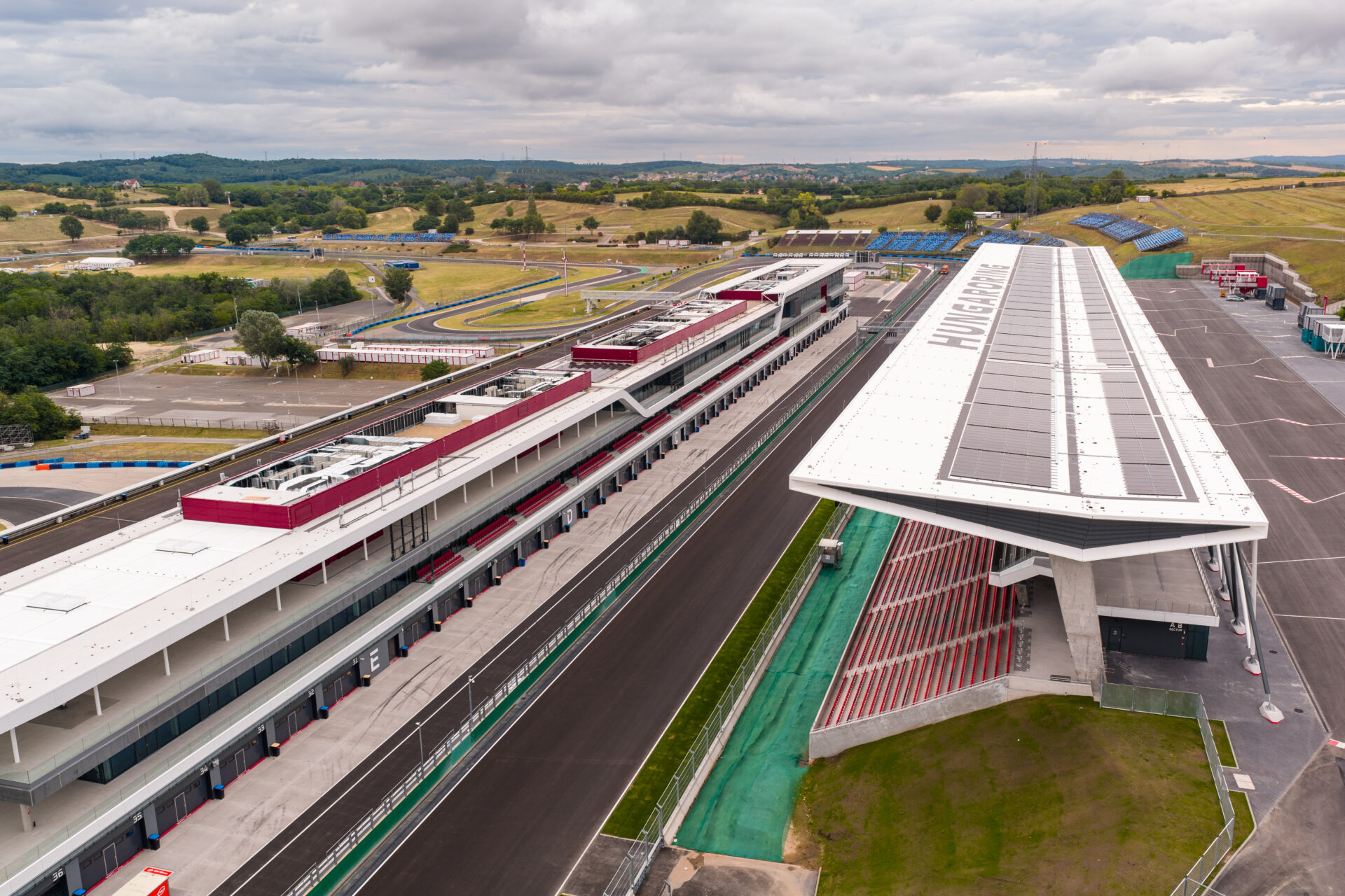
A grandstand and paddock complex: one RF zone per coverage area, not one antenna per receiver
Large venues break wireless systems in a specific way: the distance between the transmitter and the receiver changes constantly as people move, and a single fixed antenna pair cannot serve a geometry that keeps changing. The fix is zoning - dividing the venue into coverage areas, each with its own antenna pair - and understanding what the receiver's true diversity circuitry actually does with those antennas.
This article separates the two concepts that get conflated in brochures: true diversity (what a receiver does with two antennas) and zone design (how many antenna pairs a venue needs and where they go). Both matter; neither substitutes for the other.
Why Does One Antenna Pair Stop Working in a Big Venue?
Two physical effects compound with distance. Free-space loss: every doubling of distance costs signal, so a transmitter 120 metres from the antennas arrives far weaker than one at 30 metres - our working distance guide quantifies the basics. Multipath cancellation: in a large venue the signal reaches the antenna by several reflected paths, and at certain positions the reflections cancel the direct path almost perfectly - a fixed-position null that no amount of transmitter power removes.
A single antenna pair can only be aimed at one geometry. The moment performers, cameras and audiences spread across a stadium or grandstand, the correct unit of design stops being "the receiver" and becomes "the zone".
What Does True Diversity Reception Actually Switch Between?
True diversity means the receiver carries two complete receive chains on two antennas and selects - sample by sample - whichever antenna is currently receiving the transmitter better. When a performer walks into a null on antenna A, antenna B has typically already taken over; the audio never hears the transition. The concept, and how it differs from antenna-switching or single-antenna designs, is unpacked in true diversity vs antenna diversity.
The hardware expression is simple: every true-diversity receiver exposes two antenna connectors. The UR-2Q carries dual BNC inputs with +12 V/150 mA bias per channel on its rear panel, as do the HR-32D and UR-280. Those two connectors are not decorative - they are the input side of the diversity switching that masks multipath nulls.
But diversity only escapes nulls between two antennas. It cannot fix a venue where both antennas are 100 metres away from half the show. That is what zoning is for.
How Do You Design Zones in a Large Venue?
Divide the venue by where transmitters actually operate: stage zone, pit zone, grandstand zone, backstage zone. One antenna pair per zone, placed inside that zone at elevation, aimed at the positions transmitters occupy. Receivers rack together in the control position and take their feeds from the zone hardware through distribution.
The antenna hardware follows zone size. A passive panel such as the R-20U - 600-900 MHz, 7 dBi gain, an 80-degree horizontal by 60-degree vertical beam - covers one zone cleanly at mid distances. Where the zone is deep or the cable run to the rack is long, the active R-32AU (470-950 MHz, at least 6.5 dB antenna gain, 0-15 dB adjustable amplifier, noise below 0.45 dB) restores signal over the run, powered over its own coax at 75 mA so no mains is needed at the antenna.
Sharing one zone's antenna pair across receivers is the distributor's job: the R-14D feeds four receivers at 0 dB (plus or minus 1 dB) per port across 500-950 MHz, and biases remote powered antennas at +12 V DC / 150 mA per port. The passive R-12S divider serves two-to-four-receiver zones without any power at all, at the cost of 3.5 dB per split. Full arithmetic in the antenna distribution guide.
Zone planning reference
| Venue element | Zone hardware | Feeds |
|---|
| Stage / pit (one geometry) | 1 x R-20U pair or R-32AU pair | 2-4 receivers via R-14D or R-12S |
| Grandstand / long field | 1-2 x R-32AU (active, aimed per seating block) | Up to 4 receivers per R-14D |
| Backstage / artist areas | 1 x R-20U (discriminates against FOH traffic) | 2 receivers via R-12S |
| Whole venue | One zone per coverage area | Receiver rack in control position, one plan |
What Does a Grandstand Deployment Look Like in Practice?
The pattern in one sentence: active directional antennas positioned to overlook the grandstand and paddock, so that a small set of antenna pairs - one per zone - serves every receiver in the event. In the grandstand deployment shown on our engineering pages, that architecture carried a nine-receiver event from one aimed pair per zone: nine receivers, two antenna cables per zone, one control rack. Nine antenna pairs bolted to the rack would have meant nine cable runs, nine aiming jobs and nine things to re-tune; the zoned design means one.
The receiver side of the same principle is chassis density: true-diversity receivers in 1U quad or dual chassis keep the rack at two or three units for an entire grandstand programme, with the 130 MHz tuning band absorbing whatever the shared spectrum at an event site produces.
What Should You Check After Installing a Zoned System?
- Walk every transmitter position with all systems live - the zone map is proven by positions, not by the plan
- Verify both diversity antennas per receiver are actually connected (a single-antenna "true diversity" receiver is the most common install defect)
- Check bias voltage at the antenna end for powered antennas (+12 V/150 mA budget per port)
- Keep per-zone frequency plans: two zones sharing a carrier at different signal strengths is a phantom-interference generator
- Re-walk after every rigging change - a new LED wall is a new multipath geometry


